
Quick answer: The Apollo command module was the cone-shaped, three-person capsule that served as the crew’s control room and the only part of the Apollo lunar spacecraft designed to bring astronauts safely through Earth’s atmosphere. During flight it was joined to a cylindrical service module, which provided major propulsion, electrical power, oxygen and other supplies. Together, they were called the command and service module (CSM). The lunar module was a different vehicle built for landing on the Moon.
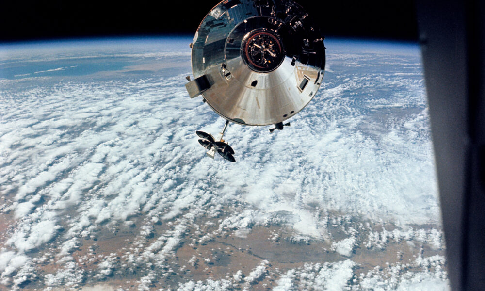
The photographs below show actual Apollo command/service modules during flight—not computer renderings. They reveal why the distinctive silver cylinder is much larger than the returning capsule.
What is the Apollo command module?
NASA’s Apollo program used the command module as the pressurized cabin for three astronauts. It housed flight displays, guidance controls, crew couches, communications equipment, environmental-control hardware and the docking tunnel. Its broad base was protected by a heat shield for reentry, while a parachute recovery system was housed toward the nose.
A common source of confusion is terminology: command module means the cone-shaped crew compartment; service module means the attached cylinder behind it; and CSM means both vehicles combined. Apollo missions regularly photographed the full CSM, even when descriptions informally say ‘command module.’
| Part | Main job | Returned to Earth? |
|---|---|---|
| Command module (CM) | House three astronauts, guidance, reentry protection and landing system | Yes: splashed down under parachutes |
| Service module (SM) | Provide the main engine and major power, oxygen and other support systems | No: separated and was discarded before Earth reentry |
| Lunar module (LM) | Carry two astronauts between lunar orbit and the lunar surface | No: not built for atmospheric reentry |
Real Apollo command module photos: what you are looking at
Featured photo: Apollo 9’s Gumdrop command/service module photographed in Earth orbit by astronauts in the lunar module Spider in March 1969. The circular face toward the camera is the command module’s docking end; the cylindrical service module extends behind the cone. NASA identifies the original frame as AS09-24-3657. It is a real mission photograph, not an artist’s impression.
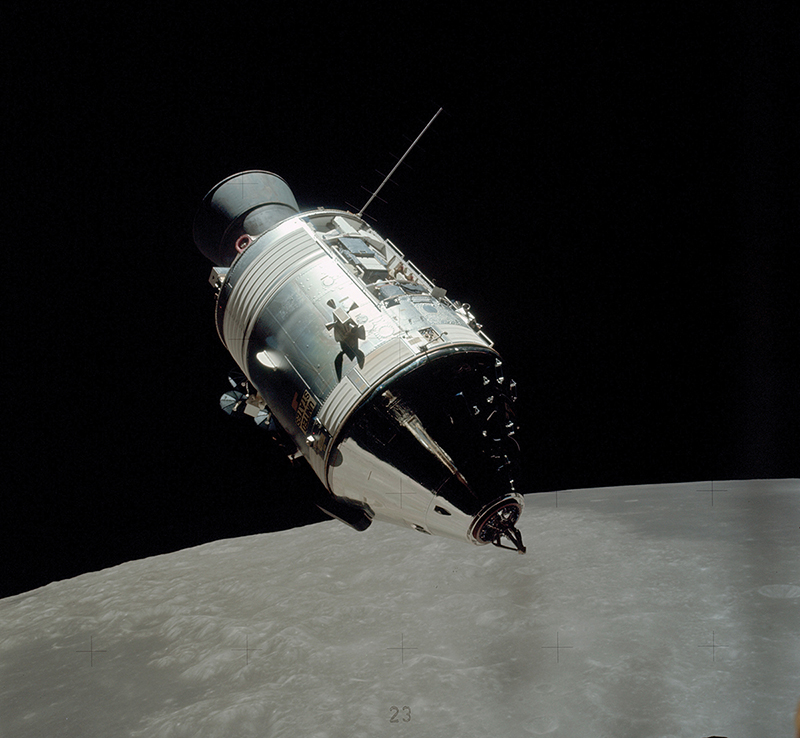
This second archival NASA photograph shows an Apollo command/service module above the lunar surface. Look for the cone-shaped crew capsule at the forward end and the much longer attached service section. Apollo’s lunar-orbit photographs were made before the service module was jettisoned.
How the command module worked on the way to the Moon
1. Launch and transposition
During a typical lunar-landing mission, a Saturn V placed the Apollo spacecraft on its translunar trajectory. The command/service module then separated from the rocket adapter, turned around, docked with the lunar module stored behind it and drew that vehicle free. This maneuver is often called transposition, docking and extraction. It created the docked stack used on the journey to the Moon.
2. Living and flying in the capsule
The three astronauts worked in the command module. Its cabin was compact: the crew could operate checklists, monitor systems, communicate with controllers and use the onboard computer, but the craft was not a spacious space station. For missions that landed on the Moon, one astronaut remained in lunar orbit in the CSM while two descended in the lunar module.
3. Power and propulsion from the service module
The service module supplied the large Service Propulsion System engine used for major maneuvers, such as lunar-orbit insertion and departure on many missions. It also carried important life-support supplies and electrical-generation hardware. The command module had its own thrusters and batteries for essential operations, especially the final return to Earth, but could not replace the service module’s entire flight capability.
4. Reuniting after a landing
After lunar exploration, the ascent portion of the lunar module met and docked with the command module in orbit. The returning astronauts transferred back into the CM and the lunar module was left behind. The CSM then continued toward Earth.
Why did the command module survive reentry while the service module did not?
The base of the command module incorporated an ablative heat shield. During the high-speed return from the Moon, the heat-shield material absorbed enormous thermal loads partly by charring and eroding in a controlled way. The crew-facing interior remained protected by the spacecraft’s layered structure and environmental systems.
NASA’s Apollo 11 recovery history describes the command module separating from the service module before reentry, orienting its heat shield toward the direction of travel and descending through the atmosphere. The returning spacecraft subsequently deployed drogue and main parachutes, then landed in the Pacific Ocean for recovery. The service module was never meant to accompany the crew all the way down.
- Prepare: Check the entry systems and configure the capsule for independent flight.
- Separate: Discard the cylindrical service module before the dangerous entry phase.
- Protect: Enter with the command module’s large heat shield positioned to absorb heating.
- Slow: Use atmospheric drag and the parachute system to reduce descent speed.
- Recover: Splash down and bring the astronauts aboard a recovery vessel.
There was no controlled runway landing and no attempt to bring the lunar module down through Earth’s atmosphere.
Apollo command module vs. lunar module: the key differences
| Question | Command module | Lunar module |
|---|---|---|
| Who occupied it? | All three astronauts during transit; command-module pilot stayed aboard in lunar orbit | Two astronauts for a lunar landing |
| Main environment | Space and the final descent through Earth’s atmosphere | Vacuum near and on the Moon |
| Shape | Compact cone with broad heat-shield base | Irregular two-stage lander with legs on the descent stage |
| Could it land on the Moon? | No | Yes |
| Could it safely return through Earth’s atmosphere? | Yes | No |
The distinction explains why you can see a lunar module in some mission pictures and a command/service module in others: they performed complementary jobs. For the engineering challenges of Apollo’s guidance software, AVARIXO also has a separate article on the Apollo 11 computer alarms and Margaret Hamilton’s team’s software. That is a software history, not a substitute for understanding the vehicle hardware.
How Apollo 9, Apollo 11 and Apollo 13 used the command module differently
Apollo 9: a full rehearsal in Earth orbit
Apollo 9 tested essential lunar-module and CSM operations in Earth orbit before the first landing attempt. The first photograph in this guide comes from that mission. Its value is that it shows a real flown command/service module in precisely the configuration used before lunar landing missions: the cone and service cylinder still joined together.
Apollo 11: a lunar landing and a returning capsule
During Apollo 11, Michael Collins remained with the command/service module Columbia while Neil Armstrong and Buzz Aldrin landed in Eagle. Once the lunar crew returned to orbit and transferred aboard Columbia, the astronauts flew home. Only the Columbia command module went through atmospheric reentry and splashed down on July 24, 1969.
Apollo 13: a service-module failure
Apollo 13 demonstrates how crucial the service module was. The oxygen-tank failure compromised the spacecraft’s intended supply systems, causing NASA to abandon the planned Moon landing. The lunar module was used as an emergency lifeboat for much of the return. Nevertheless, the crew ultimately needed the command module, with its heat shield and parachutes, for the final Earth-entry phase.
Why don’t we have photographs of the service module after splashdown?
Because the service module was separated before Earth reentry. Recovery teams retrieved only the command module. Museums today exhibit various real Apollo command capsules; full CSM displays may involve a replica service module or an engineering article. When identifying a historical photo, ask whether it shows a flown spacecraft, a ground-test article or a modern reconstruction.
Common mistakes when identifying Apollo images
- Confusing the command module with the entire CSM: the crew capsule is the cone, not the entire cone-and-cylinder assembly.
- Calling the lunar module an ‘Apollo capsule’: the lunar module was a two-stage vehicle designed for the Moon’s airless environment.
- Assuming every NASA illustration is an in-flight photograph: check the original photo number, caption and mission archive. The images here are archival spacecraft photographs.
- Thinking the service module splashed down: it was discarded before reentry.
- Mixing up a spacecraft photograph with lunar imagery: an orbiter photograph and a photograph taken by an orbiter are different things. For modern lunar science, see AVARIXO’s Artemis II image-and-data explainer.
Frequently asked questions
How many people fit inside an Apollo command module?
Three astronauts. Lunar landing crews traveled together in the CSM, then two used the lunar module for the surface trip while one stayed in lunar orbit.
Was the Apollo command module the same as the lunar module?
No. The CM was the Earth-return capsule; the LM was the separate lunar lander. They docked so astronauts could transfer between them.
What was the silver cylinder attached to the Apollo capsule?
That was the service module, which supplied major power, propulsion and life-support resources during the mission.
Did the Apollo command module have an engine?
It had small reaction-control thrusters; the large engine used for major mission maneuvers was part of the service module.
Is the Apollo 9 photograph a genuine image?
Yes. NASA/JSC catalogs AS09-24-3657 as an Apollo 9 mission photograph of the command/service module Gumdrop, taken by astronauts aboard the lunar module Spider.
Why was the cone shaped?
Its broad base gave the capsule space for a substantial reentry heat shield, while the compact pressurized compartment and recovery system fit within the flight profile and launch-vehicle constraints.
Research note: Historical spacecraft identification and reentry details were checked against NASA/JSC’s Apollo 9 image archive and NASA’s Apollo 11 and Apollo 13 mission histories. Image source records and reuse information are held in the AVARIXO media library; no generated illustration is presented as an authentic flight photograph.